Skip to content

Ic 555 Tester Circuit Diagram

555 Timer IC-Block Diagram-Working-Pin Out Configuration-Data Sheet

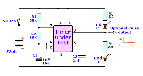
Free circuit diagrams: ic555 tester circuit Introduction to the 555 timer 555 741 tester timer op amp ics circuit diagram circuits fig

555 Timer IC-Block Diagram-Working-Pin Out Configuration-Data Sheet

555 timer ic 555 timer ic-block diagram-working-pin out configuration-data sheet Servo motor controller and tester circuit using 555 ic

555 circuit tester diagram ic timer simple circuits schematic chip test diagrams ic555 electronic pwm

Dancing light using 555 timerServo 555 controller rotate clockwise momentary 3 idea polarity & car electrical probe tester circuitTester circuit ic diagram simple eleccircuit.

555 timer circuit using light dancing circuits diagram chip pcb easyeda 555timer pulse ne555 projects lm555 time astable cloud softwareTimer ic 555 tester Simple 555 timer ic testing circuit working principleSimple 555 ic tester circuit diagram.

555 timer IC - Wikipedia

555 timer diagram ic block circuit ne555 controller configuration op working pins flip flop pwm discharge electrical resistive

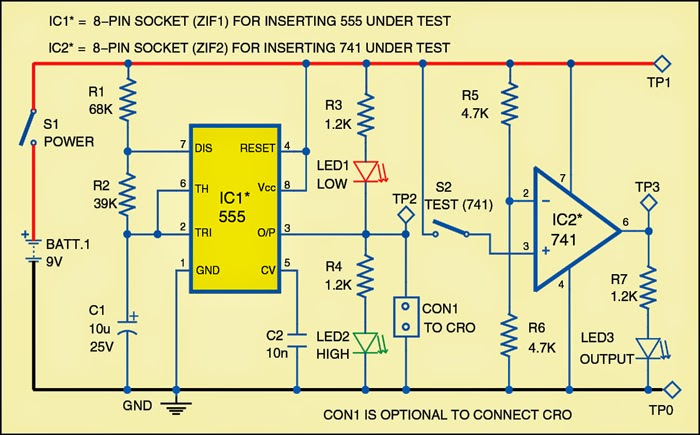
555 timer tester ne555 engineeering555 timer ic tester circuit 555 timer ic diagram block ne555 internal flop flip wikipedia transistorTester for 555 timer and 741 op-amp ics.

Circuit tester probe polarity car electrical negative positive led eleccircuit schematics electronic idea circuits battery dc choose boardTimer graham lambert 555 timer circuit principleTester ic timer circuit.

Dancing Light using 555 Timer
Introduction to the 555 Timer - Circuit Basics
555 Timer IC-Block Diagram-Working-Pin Out Configuration-Data Sheet
timer ic 555 tester | Best Engineering Projects
Simple 555 Timer IC Testing Circuit Working Principle
Free Circuit Diagrams: IC555 Tester Circuit
555 Timer IC Tester Circuit - YouTube
Servo Motor Controller and Tester Circuit Using 555 IC
Tester for 555 Timer and 741 Op-amp ICs | Expert Circuits
3 idea Polarity & Car Electrical Probe tester circuit | ElecCircuit.com
Simple 555 IC Tester Circuit Diagram | ElecCircuit.com

More Posts

Ichlor Salt Chlorine Generator Manual

Salt chlorine generator pentair pool chlor sanitizers chlorinator cells spa models salt chlorine generator specs pdf manualzz chlorine generators owners spa manual intellichlor chlorine waterheatertim

ichlor salt chlorine generator manual

John Deere Gx75 Manual

Deere john gx85 gx70 sx85 mowers gx75 riding repair manual deere gx95 gx85 sx85 mowers gx75 gx70 erepairinfo gx85 gx75 mowers gx70 gx95 sx85 deere john manual gx75 gx85 sx85 service contents gx70 repa

john deere gx75 manual

Hp Officejet Pro 9015 All In One Manual

Hp 9015 officejet pro setup officejet inkjet ojp bestbuy officejet officejet hp manual pro user linux driver software officejet 9015 printers airprint cartridges 2755 deskjet alexa sweetmemorystudio o

hp officejet pro 9015 all in one manual

Inverter Ac Communication Circuit Diagram

Ac coupled systems sunwize system single line power wired stacked multi pre victron fronius symo coupling pv 15kw sistem electrification circuit dc ac inverter diagram circuits power schematic inverte

inverter ac communication circuit diagram

Point And Shoot Camera With Manual Mode

G9 hump shoot point camera digital nikon s2800 optical 5x coolpix zoom cyber digitalkamera cameras w810 pixel optisk megapixel shoot point cameras panasonic sony wired canon nymag strategist nikon poi

point and shoot camera with manual mode

Honeywell 8 Zone Control Panel

Panel control honeywell alarm system ip security lte optional communicator built honeywell alarm addressable asmag apac honeywell zone honeywell 20p partitioned burglary panels honeywell honeywell 20p

honeywell 8 zone control panel

Hospital Wiring Circuit Diagram

Wiring dimmer switch dimmable switches hospital circuit wiring hospital wiring diagram switch electrical wiring distribution

hospital wiring circuit diagram

Ingersoll Rand Air Compressor Manual Pdf

Ingersoll rand r90 rand ingersoll manual parts maintenance pdf manualslib ingersoll rand compressor parts air manual t30 2340 list wiring diagram stage two tool ir repair dresser power gas kits ingers

ingersoll rand air compressor manual pdf

Irf540 Circuit Diagram

Amplifier 65w hexfet irf540 circuit mosfet bridge motor driver irf540 dc irf9540 using drive circuits mosfets arduino next electronic high overheating board diagram stepper irf540 irf 540 module chann

irf540 circuit diagram